
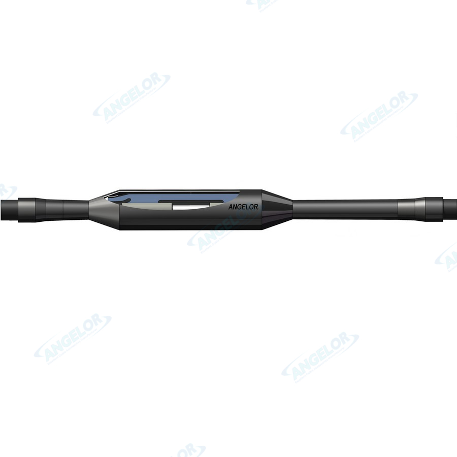
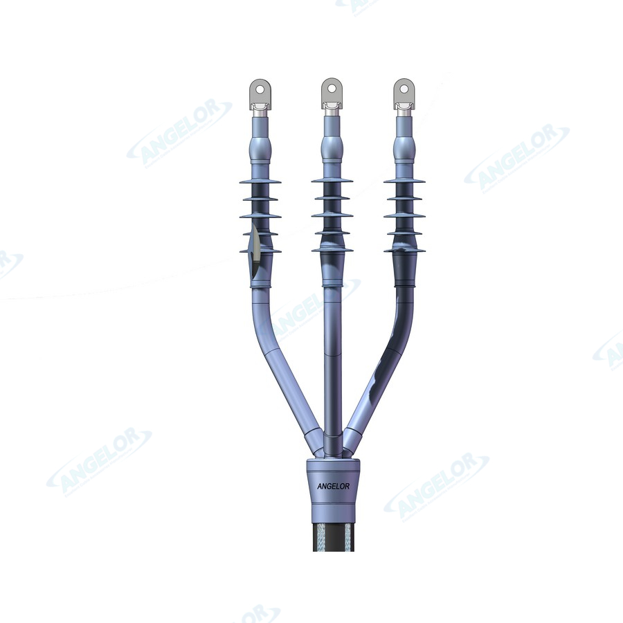
The premolded stress cone, designed using geometrical electric field control and combine with sufficient interface pressure, ensures uniform electric field distribution and long-term reliable operation;
With sufficient electrical margin;
Have excellent sealing performance with armor tape as normal;
Mature design with long-term successful service experience.
Application
• Designed for the connection of MV power cables;
• Suitable for underground tunnels, direct burial installations (protective box recommended), and installation on cable racks or supports;
• Applicable for connecting different cable cross-sections within a certain range of MV cable systems.
Compatible Cables
• Cable type: XLPE or other polymer-insulated, single or three cores MV power cables;
• Metallic Screen: Copper tape, Copper wires, Al wires, Al foil tape and etc.
Product Application Standards
Applicable standards: IEC 60502-4,GB/T 12706.4.
Technical Data
| Item | Technical Specifications |
Voltage Level(kV) | 6/10 (12) kV |
Rated Voltage (U₀ / U) | 6/10 kV |
Highest System Voltage (Uₘ) | 12kV |
Partial Discharge Test (pC) | At 1.73 U₀: no detectable PD above the specified sensitivity |
Power Frequency Withstand Voltage (KV) | At 4.5 U₀ for 5 min, no breakdown or flashover |
Lightning Impulse Withstand Voltage | 75 |
Overall Dimensions (L × Ø) | 420*51 |
Net Weight (excluding cable) | 10 |
Optional Solutions
• The connector between cable conductors could be crimp or mechanical type.
• Optional protective box according to installation conditions.
• Sectionalized Joint design can be used for longer circuit with outer earthing system.
Operating Conditions
• Ambient temperature: –45 °C to +45 °C
• Installation altitude: No limitation.
Storage Conditions
• Optimal Storage Temperature: 10°C to 25°C
• Indoor with dry and clean environment, keep sealing and avoiding ≥4 layers overlap.
Available Straight Joint Selection (Recommended selection based on cable insulation diameter)
Voltage Level(kV) | Product Type | Conductor Size Range (mm²) | Cable Insulation Diameter (mm) | Protective Housing |
6/10/12 | JLS-6/10-1x25~50 | 25~50 | 16.4~18.5 | W/O protective housing |
6/10/12 | JLS-6/10-1x70~120 | 70~120 | 20.2~23.2 | |
6/10/12 | JLS-6/10-1x150~240 | 150~240 | 24.8~28.8 | |
6/10/12 | JLS-6/10-1x300~400 | 300~400 | 30.8~34 | |
6/10/12 | JLS-6/10-1x500~630 | 500~630 | 36.8~40.2 | |
6/10/12 | JLS-6/10-3x25~50 | 25~50 | 16.4~18.5 | |
6/10/12 | JLS-6/10-3x70~120 | 70~120 | 20.2~23.2 | |
6/10/12 | JLS-6/10-3x150~240 | 150~240 | 24.8~28.8 | |
6/10/12 | JLS-6/10-3x300~400 | 300~400 | 30.8~34 | |
6/10/12 | JLS-6/10-3x500~630 | 500~630 | 36.8~40.2 |
Note:It can be customized based on cable section and insulation diameter if the Termination's specification is outside the above ranges.
Copyright © 2026 Angelor (Jiangsu) Intelligent Electric co.,LTD.